24 Port PoE Switch: When Does a 10G Uplink Make Sense?
6 Visits
A 24 port PoE switch does not automatically need a 10G uplink. A 1G uplink can be appropriate when connected devices generate light or intermittent traffic and measured utilization leaves comfortable headroom.
It becomes a shared choke point when sustained aggregate traffic or bursts approach its usable capacity. Evaluate 10G when cameras, wireless access points, servers, or other endpoints create higher sustained loads, when resilience matters, or when expected growth could make 1G a near-term constraint.
The correct decision starts with three separate questions: How much traffic will the endpoints actually generate? How much PoE power must be available simultaneously? And what uplink medium and redundancy design will meet the network's distance and availability requirements?
What Happens When 24 Gigabit Ports Share a 1G Uplink?
Access-port speed is not the same as actual endpoint traffic.
Twenty-four 1Gbps access ports represent twenty-four interfaces capable of operating at Gigabit Ethernet speeds. They do not mean twenty-four devices will continuously generate 24Gbps of traffic. Actual utilization depends on device workload, traffic direction, application behavior, concurrency, and the amount of traffic that must cross the uplink.
However, if all twenty-four 1Gbps ports need to send through one 1Gbps uplink, the theoretical port-to-uplink oversubscription ratio is 24:1:
24 × 1Gbps access ports ÷ 1Gbps uplink = 24:1
For sixteen Gigabit access ports sharing the same uplink:
16 × 1Gbps ÷ 1Gbps = 16:1
These are theoretical ratios, not predictions of real traffic.
Oversubscription is normal in many Ethernet designs. It becomes a problem when sustained aggregate traffic approaches the uplink's usable capacity or when simultaneous bursts create contention. Frames may then be queued, increasing latency, and sufficiently persistent congestion can lead to packet loss.
The 1Gbps Ethernet line rate should also not be treated as guaranteed application throughput. Ethernet frames and higher-layer protocols add overhead, and the real application rate depends on the traffic being transported.
Key takeaway: Choose the uplink based on measured or reasonably projected aggregate traffic, not access-port count alone.
How IP Cameras Can Create Aggregate Traffic Bottlenecks
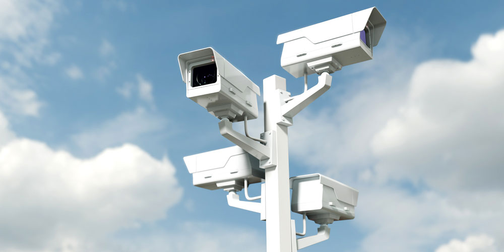
A surveillance PoE switch can produce relatively consistent upstream traffic because many cameras transmit video toward recorders, analytics systems, or monitoring platforms at the same time.
There is no universal bandwidth value for an IP camera. Traffic varies with resolution, frame rate, codec, compression settings, scene complexity, continuous versus event-based recording, simultaneous streams, multicast versus unicast delivery, and analytics or metadata.
For planning, engineers can start with:
Number of devices × assumed average traffic per device = estimated aggregate traffic
The following figures are hypothetical planning examples only. They are not guaranteed camera bitrates or measured FlexSwitch performance.
Connected devices
Assumed average traffic per device
Estimated aggregate traffic
Likely condition on a 1G uplink
Evaluate 10G?
12
4 Mbps
48 Mbps
Substantial theoretical headroom
Usually not for bandwidth alone
24
8 Mbps
192 Mbps
Significant headroom remains
Usually not for bandwidth alone
24
20 Mbps
480 Mbps
Moderate utilization; examine peaks and other traffic
Consider if growth or bursts are expected
24
35 Mbps
840 Mbps
Limited headroom once bursts and protocol overhead are considered
Yes
24
50 Mbps
1,200 Mbps
Aggregate demand exceeds a single 1Gbps link rate
Yes
These calculations demonstrate why camera count alone is insufficient. Twenty-four efficiently compressed streams could fit comfortably through 1G, while a more demanding video design could approach or exceed that uplink.
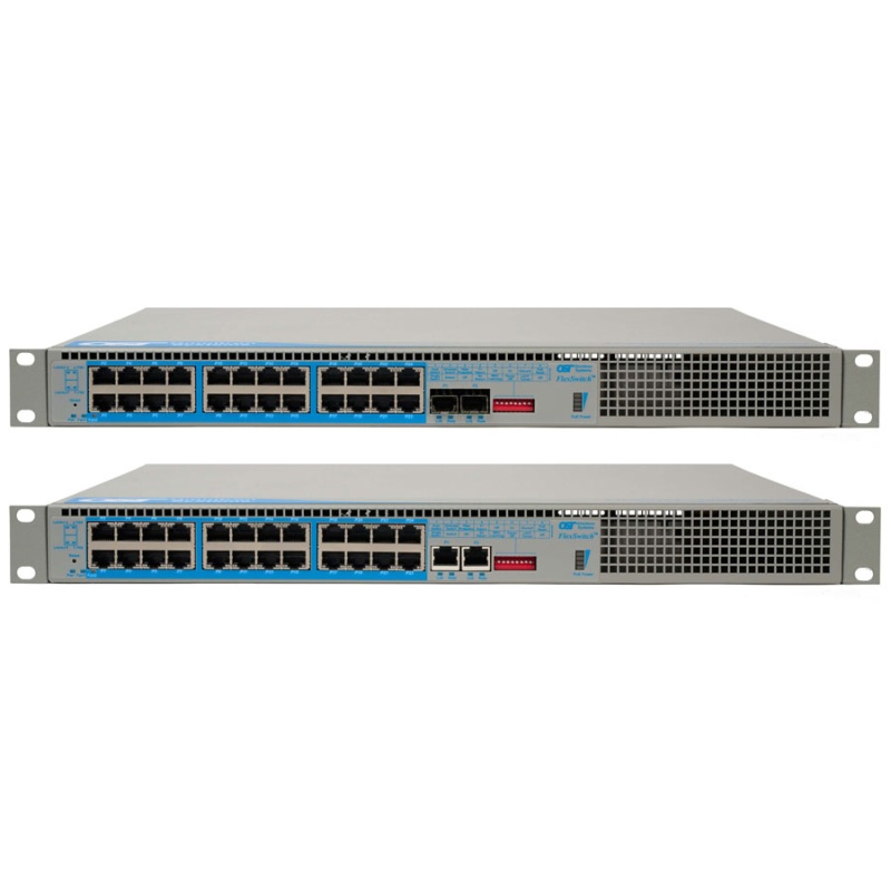
Explore the FlexSwitch 10GRPoE+/Sx and compare 1G, 10G, fiber, and copper uplink configurations. The switch provides two uplink ports with 1/10G SFP/SFP+ or multi-gigabit/multi-rate RJ-45 options.
When Does a 10G Uplink Actually Make Sense?
A 10G uplink should be evaluated when one or more network requirements make the capacity or headroom of 1G undesirable:
Sustained aggregate traffic is regularly high.
Peak traffic consumes too much of the available 1G headroom.
High-resolution video, multiple streams, or analytics create continuous upstream loads.
Multiple edge switches feed a common distribution point.
Servers, wireless access points, or other data-intensive endpoints share the access switch.
Network expansion is expected during the switch's service life.
Congestion or interruption has a high operational cost.
The organization wants an uplink upgrade path without immediately replacing Gigabit access devices.
Conversely, 1G may remain entirely appropriate when endpoint traffic is light, relatively few devices transmit simultaneously, measurements show substantial headroom, bursts are tolerable, and little capacity growth is expected.
Whenever possible, use sustained and peak utilization measurements from the existing network instead of selecting 1G or 10G from port count alone.
Fiber vs. Copper 10G Uplinks
A 24 port PoE switch with 10G uplink capability still requires a medium that fits the physical network.
Selection factor
10G fiber uplink
10G copper uplink
Transmission distance
Distance depends on fiber and transceiver selection; well suited to longer infrastructure links
Suited to compatible structured-cabling links; verify cabling and interface requirements
Electromagnetic interference
Fiber is not affected by electromagnetic interference in the same way conductive copper cabling is
Installation should account for the electrical environment and appropriate cabling
Cabling/transceivers
Requires compatible SFP/SFP+ optics and matching fiber
Requires compatible RJ-45 interfaces or copper transceivers and qualified cabling
Environment
Useful between buildings, across campuses, and in electrically challenging locations
Practical for nearby equipment, telecom rooms, and existing copper infrastructure
Heat/power considerations
Verify optical-module power and thermal requirements
Verify the thermal and power requirements of 10G copper interfaces/transceivers
Upgrade flexibility
Pluggable optics can support different fiber types and infrastructure requirements
Can reuse suitable existing copper infrastructure where requirements are met
Typical fit
Backbone, campus, building-to-building, longer distribution links
Shorter local equipment and rack/room connections
Fiber is not automatically better, and copper is not automatically cheaper once the entire installation is considered. Evaluate distance, existing cable plant, transceiver requirements, electrical environment, future migration plans, and total deployment cost.
The FlexSwitch 10GRPoE+/Sx supports either 1/10G SFP/SFP+ uplinks or multi-rate RJ-45 uplinks operating at 100Mbps, 1Gbps, 2.5Gbps, 5Gbps, or 10Gbps, depending on configuration.
Why Redundant 10G Uplinks Matter in Critical Networks
Higher bandwidth and redundancy solve different problems.
A second uplink does not automatically turn two 10G interfaces into one 20Gbps connection. Total usable capacity depends on operating mode, topology, failover behavior, and the upstream network design.
Redundant uplinks are intended to preserve connectivity when a primary path fails. For resilience to be meaningful, engineers should also consider physical path diversity and upstream failure domains. Two cables routed through the same conduit or connected into the same vulnerable infrastructure may still share a single point of failure.
This matters in government, security, campus, enterprise, and other networks where restoring communications after disruption is a design requirement. NIST's cyber-resiliency engineering guidance similarly frames resilience around the ability of systems to withstand, recover from, and adapt to adverse conditions.
The FlexSwitch supports redundant fiber or copper uplinks and can fail over from the primary uplink to the secondary. The second uplink can alternatively be used to cascade switches.
“PoE+” Does Not Always Mean 30W Is Available on Every Port
PoE selection requires separating per-port capability from total switch power budget.
A switch may have twenty-four PoE+ ports while its total power supply cannot support the maximum PoE+ allocation on all ports simultaneously. Engineers should evaluate:
Maximum power classification of each port
Typical and maximum demand of each powered device
Total simultaneous switch PoE budget
Expected device additions
Appropriate planning margin
IEEE 802.3at defines the Ethernet PoE enhancements associated with PoE+; the IEEE 802.3at standard is the primary standards reference.
For the twenty-four-port FlexSwitch 10GRPoE+/Sx configuration, Omnitron specifies full 30W PoE+ power simultaneously to the PoE/PoE+ user ports:
24 ports × 30W per port = 720W available across the PoE ports
Power at the switch port should not be confused with the exact power ultimately available at the powered device because standards-related delivery and cabling considerations still apply.
For extended-temperature deployments, verify the selected power configuration against Omnitron's current power-budget and temperature table. The current product page shows that available PoE wattage for some AC configurations can vary at the highest operating temperatures.
How Dual Device Mode and Directed Switch Mode Improve Network Design
The FlexSwitch is an unmanaged Layer 2 switch, but two operating modes provide useful traffic-path options for specific deployments. Engineers comparing managed versus unmanaged PoE switches should evaluate these modes separately from full managed-switch features.
Dual Device Mode
Dual Device Mode operates the switch as two independent and isolated switches. On the twenty-four-port configuration, each traffic path has one uplink and twelve user ports.
Potential uses include separating two edge traffic groups, connecting them toward separate upstream destinations, limiting the effect of a failure on one traffic path, or supporting two logically distinct edge networks in one physical chassis.
Dual Device Mode should not be treated as a replacement for every VLAN, firewall, access-control, or managed segmentation requirement. If policy-based segmentation or advanced traffic management is required, evaluate whether a managed switch architecture is more appropriate.
Directed Switch Mode
Directed Switch Mode directs multicast traffic, including video, only toward the appropriate uplink rather than allowing that multicast traffic to flood other network ports.
For IP surveillance, this can reduce unnecessary camera-stream traffic on access ports and help keep multicast video focused on its intended upstream path. See how Directed Switch Mode works for additional application context.
Directed Switch Mode is a traffic-handling feature. It should not be treated as a complete cybersecurity architecture.
Where a 24 Port PoE Switch with 10G Uplinks Fits
1. Security and surveillance
A surveillance network may require sustained upstream video, full PoE+ availability for cameras, multicast handling, and fiber connectivity back to a control room. The decision for 1G versus 10G should come from estimated or measured video traffic rather than camera count alone.
2. Campus and education networks
A campus network switch may connect cameras, wireless access points, phones, access-control devices, and other endpoints in one building. Fiber uplinks can be appropriate when distribution infrastructure spans longer distances, while uplink redundancy may be important for facilities with limited maintenance windows.
3. Government and public-sector facilities
Government network infrastructure may add procurement and sourcing requirements to the technical evaluation. For organizations that specifically require them, the FlexSwitch is documented as Made in the USA and TAA, BAA, and NDAA compliant.
4. Enterprise offices, warehouses, and distributed facilities
Enterprise PoE networks often combine devices with very different traffic and power profiles. A warehouse, for example, may need continuous camera traffic while office endpoints are intermittent. Separating the bandwidth calculation from the PoE power calculation prevents an apparently adequate switch from becoming constrained in one dimension.
24 Port PoE Switch Selection Checklist
Before selecting a switch, document:
Number of powered devices
Typical and maximum power required by each device
Total simultaneous PoE power requirement
Typical and peak aggregate traffic
Required 1G, multi-gigabit, or 10G uplink capacity
Fiber versus copper uplink medium
Number of uplinks
Uplink failover requirement and physical path diversity
Multicast video handling requirements
Traffic-isolation requirements
Required operating-temperature range
AC or DC power requirements
Procurement and compliance requirements
Expected device and bandwidth expansion
Technical support or network-design assistance requirements
The FlexSwitch 10GRPoE+/Sx is an unmanaged Layer 2 option for networks requiring up to twenty-four Gigabit PoE+ access ports together with higher-speed uplink choices.
For the requirements discussed above, its relevant capabilities include:
Up to twenty-four 10/100/1000 PoE/PoE+ RJ-45 user ports
Full 30W PoE+ capability simultaneously across the twenty-four powered ports in a full-power configuration
Two 1/10G SFP/SFP+ fiber or multi-rate copper uplinks
Dual Device Mode
Directed Switch Mode
Redundant-uplink capability
Configurable PoE Power Reset for devices such as cameras and wireless access points
Commercial, wide-temperature, and extended-temperature versions
Made-in-USA manufacturing with documented TAA, BAA, and NDAA compliance
These features are useful when the design problem involves a combination of PoE density, aggregate traffic, fiber or copper uplink selection, resilience, and procurement requirements rather than port count alone.
Conclusion: Start With Traffic, Power, and the Uplink Path
Choosing a 24 port PoE switch should come down to three engineering checks.
First, measure or estimate aggregate traffic and determine whether 1G provides enough sustained and peak headroom. Second, verify that the total PoE power budget can support all required devices simultaneously. Third, design the uplinks around distance, medium, resilience, and expected growth.
A 10G uplink is valuable when the traffic profile or network design justifies it. It is not a requirement simply because the switch has twenty-four Gigabit ports.
1. Is a 1G uplink enough for a 24 port PoE switch?
Yes, a 1G uplink can be enough when connected devices generate relatively light or intermittent traffic and measured peak utilization leaves sufficient headroom. Port count by itself does not determine uplink demand. If sustained aggregate traffic begins approaching the practical capacity of the link, or bursts regularly create congestion, a 10G uplink should be evaluated.
2. Can 24 Gigabit ports overload a 1G uplink?
Yes. If twenty-four Gigabit access ports all need to transmit through the same 1G uplink, their theoretical port-to-uplink oversubscription is 24:1. That does not mean the network will actually generate 24Gbps. Problems arise only when the endpoints' combined real traffic creates sustained or burst demand beyond what the shared uplink can carry.
3. How much bandwidth do 24 IP cameras need?
There is no universal bandwidth requirement for twenty-four cameras. Calculate it from the camera configuration and deployment. Resolution, frame rate, codec, compression, scene complexity, recording mode, simultaneous streams, multicast or unicast delivery, analytics, and metadata all affect traffic. For planning, multiply an assumed or measured average bitrate per camera by the number of simultaneously active cameras, then evaluate peak demand and headroom.
4. Does every PoE+ switch provide 30W on all ports?
No. A switch can support PoE+ on each individual port without having enough total PoE budget to allocate maximum power to every port simultaneously. Technical buyers should check both the per-port PoE capability and the switch's total simultaneous power budget, then compare those values with the actual requirements of the connected powered devices.
5. What is the total PoE budget for 24 ports at 30W each?
Twenty-four ports at 30W each require 720W of port power capacity.
24 × 30W = 720W
The twenty-four-port FlexSwitch 10GRPoE+/Sx supports this full-power configuration. For installations at elevated operating temperatures, verify the selected model, power option, and current Omnitron temperature/power table because available wattage can depend on operating conditions.
6. Is fiber or copper better for a 10G uplink?
Neither medium is universally better. Fiber is often appropriate for longer backbone, campus, building-to-building, or electrically challenging links. Copper can be practical for shorter connections where suitable structured cabling and compatible interfaces already exist. Choose based on distance, existing infrastructure, transceiver requirements, electromagnetic environment, thermal considerations, upgrade plans, and total installed cost.
7. Do two 10G uplinks provide 20Gbps of bandwidth?
Not automatically. Two physical 10G interfaces do not inherently operate as one 20Gbps logical connection. Their function depends on switch capability, operating mode, topology, and upstream network design. On the FlexSwitch, the uplinks may serve functions such as redundancy, separate Dual Device Mode traffic paths, or cascading. Do not assume bandwidth aggregation without a design that specifically supports it.
8. What is Dual Device Mode?
Dual Device Mode allows the FlexSwitch to operate as two independent and isolated switches. In the twenty-four-port configuration, one uplink and twelve user ports are assigned to each independent traffic path. It can support traffic separation or separate upstream destinations, but it should not be treated as a universal replacement for managed VLANs, firewalls, or policy-based network segmentation.
9. What is Directed Switch Mode?
Directed Switch Mode controls how multicast traffic is forwarded. On the FlexSwitch, multicast traffic such as video is directed only to the appropriate uplink, helping prevent multicast video from flooding other network ports. This can be useful in surveillance deployments by reducing unnecessary traffic exposure on access ports, but it is not a complete network-security solution.
10. When are redundant uplinks necessary?
Redundant uplinks should be considered when loss of a single uplink would create unacceptable operational disruption. This may apply to security, government, campus, enterprise, industrial, or other critical networks. Effective redundancy also requires attention to physical path and upstream diversity. Two links that share the same vulnerable conduit, power source, or upstream failure domain may still leave a common point of failure.